Tuesday, December 23, 2008

WisDOT Template-in-Progress

Lots of my users have been asking about the WisDOT draft Civil 3D template. My friends at the DOT have given me the green light to post the link to the FTP site where the template-in-progress can be found.

Keep in mind that this is NOT the final cut and that they are posting updates every month or so.
I'm told the final cut should be available in fall 2009.

ftp://ftp.dot.state.wi.us/transp/roads/civil3d/

Enjoy and Happy Holidays!

Thursday, December 18, 2008

Quick, Non-technical Update

As the Holiday season approaches I am spending more free time making Yule logs and wrapping presents than blogging - so I apologise to my adoring, somewhat neglected following.

I've got my hands elbow deep inside a Map 3D implementation project and I've been ramping up to be the next Revit Architecture guru at my company. Oh! I've always wanted to make a family!

Dare I say I'm Tuckered out?

So just a few shout-outs to keep the hits up:
Ladd Nelson of Carlson Software - it was AWESOME to see you last weekend. I could really use another margarita.

Anne Gerriets of Eagle Point - break a leg sista' and I don't mean on the Iowa ice!

Peace and love to everyone else. I'm planning on posting a real post before Christmas.

Wednesday, December 10, 2008

Back to Basics: Panning, Zooming and Selecting Stuff

This week I conducted a class in which one of my students did not want to use the middle mouse wheel to pan and zoom. She wasn't using Autocad with MBUTTONPAN set to 0, she just was used to right-clicking all the time to get there. I gave up trying to coax her into using the middle mouse wheel when she said, "..But all that panning and zooming makes me seasick!"

The problem arose when creating Civil 3D objects - many of the Civil 3D commands treat any right-click as ENTER. When we were creating Profiles by Layout, for example, she would try to pan over and set a PVI, but her right-click kicked her out of the layout tools. Watching her use the scrollbars to pan thereafter was nothing short of painful.

So, in short:
  • Roll forward to zoom in.
  • Roll Back to zoom out.
  • Wherever your cursor happens to be is where Autocad is aiming for the center of your view to be.
  • Double-click the mouse wheel as if it were a button for zoom-extents.
  • Push and hold the mouse for panning.
A little Dramamine and you're production speed will double!


Selecting Sh*t:

I'm always surprised at how many people still don't know this after years of CAD work.
By default Autocad (and by association, Civil 3D) you are in a selection mode if you are not in a command. (If you came from Microstation, this fact is a hard one to get used to).

A Left to Right crossing window only selects items that are completely inside the selection window.


A Right to Left crossing window selects items that are inside the selection window as well as items that touch the dashed line.
And that's just outside of a command.
Now, let's say you are in a command. Let's take the Civil 3D command Delete Lines iinside the surface editing tools, for example. At the Select Edges: prompt, type F for fence, then enter. You now are in fence mode and can click around to make a temporary line. Anything that touches this line becomes selected. Hit enter when you are done creating the fence and you can keep selecting or hit enter again to continue deleting triangle legs.

Lastly, don't be shy about using the SHIFT+SPACEBAR trick to select objects that are on top of each other. This happens all the time in Civil 3D. You have alignments under corridors, surfaces coinciding with grading objects and featurelines everywhere in between. Hover over an object until it "lights up" without clicking. If that is not the object you were aiming for, hold down the SHIFT key, then thumb the spacebar at the same time. When the object you want "lights up," click it. This is a heck of a lot faster than flipping around the Draw Order.


Thursday, December 04, 2008

In Honor of Jame's AU Presentation


Did you see James Wedding's presentation today at AU?

You should have - and this is what I think of him...

Back to Basics: Changing Your Background Color

Let me save you some time if you're a long time user of AutoCAD - browse away and come back later.


If you are a new-ish user of CAD, the following may be of interest to you.

The following instructions will work for any AutoCAD-based product pretty much any version you may have running. (Unless you are, like, in v11 DOS or some shiat)


Here are the instructions as far as changing the background color in AutoCAD:

1) Type OPTIONS at the CAD command line (or right-click anywhere on the screen and select Options from the menu).


2) Go to the Display Tab.
3) Click the Colors button.


4) Click the color pull-down and select black.


5) Click Apply and Close.
6)Last click OK to the Options box.

AutoCAD will stay this way from now on. Now if you are interested in more nitty-gritty, keep reading.

The colors and everything else inside the Options dialog box are stored in your Profile. By default, Civil 3D loads with "Unnamed Profile" and all your changes get saved there. If you like your settings and want to save yourself some time if you ever need to reinstall, you can export your Profile out to an ARG file.

I feel I've gone too far. One of these days I'll do a more detailed post on Profiles vs CUI's but for now we'll keep it simple.

Monday, November 24, 2008

SQOTD: Resolving Multiple XREFS

Q - Is there a lisp program available to redirect the saved path for xrefs when the directory changes on the network? (e.g. xrefs once located in N:\Drawings\Building\ are now found in P:\Eng\Shared\Drawings\). Looking for a better way than to doing them all manually for every drawing that gets opened.


A - There's an even better way than using a LISP routine.

There is a little-known utility that has come with AutoCAD for years that will do just what you are looking for. Look for a file named ADREFMAN.exe. This should be located in your AutoCAD folder: C:\Program Files\AutoCAD Civil 3D 200X\
[If you can't find AdRefMan.exe, look on your install DVD.]

When the manager is open, click Add Drawings. Browse to the folder where your drawings are now stored and select as many as you need.


Next, AutoCAD will ask you if you want to "Add Xrefs regardless of nesting level" or "Add only first level Xrefs". Most people should choose Add only first level Xrefs.

The manager will show you any DWG's, Images, Plot Styles or Fonts it thinks you need.

On the right hand side of the box, expand By Reference and highlight the XREFS to narrow down the listing.
Using your shift key, multi-select the unresolved XREF drawings on the right. Click Find and Replace .

Replace the old path with the new, then click Replace All.
[In this example, all of my path types were set to Relative when I created the references, therefore I am seeing just a period (.) instead of a full path for my saved path.]


Click Apply Changes at the top of the window to save the results.

You should be ready to keep working!

Friday, November 21, 2008

Expression Example

Expressions are one of those tools that you never know how you might use them until you need them.
Yesterday I found myself wanting to check to make sure some figures I created were truly at elevation. I wanted to see both the slope distance and the horizontal distance in the label. However, horizontal distance is not an option in the native list of components.

I created this expression under Settings > General > Label Styles > Line.


Right-click on the Expressions and select New. You'll see the dialog at left.

Here's the "math" that you can use to copy and paste into your expression window:


SQRT({General Segment Length}^2-(ABS({General Segment Start Z}-{General Segment End Z})^2))


Once the expression was created I made a copy of the style Bearing Over distance by right-clicking and selecting Copy. On the copy, I right-clicked and selected Edit. On the Information tab, I renamed the style to "Bearing over Distance (Horiz Dist)". On the Layout tab, I set my active component to Distance, and gave the component name a quick rename.


Then I clicked the ellipsis to get into the text component editor.


Your expression should now show up in the list of available Properties. Select Horizontal Distance, set precision and how you'd like the number to show up - then click the blue arrow to add it to the right side of the box.

Once you click OK, OK, and complete the label you can use it on lines, polylines, figures and feature lines.

However, it does not work on Alignments, Parcel Segments or 3D polylines.


Friday, November 14, 2008

SQOTD: How to Make a Copy of Your EG Profile


Q. I was wondering if there is a way in Civil 3D 2009 to make a copy of my existing ground profile 4 feet down from the original in order to show a location for my water line.


I tried to copy my existing profile but the whole toolbar is greyed out when I try to edit geometry.

A. Select your EG profile, right-click and pick Profile Properties. Switch to the Profile Data tab. Scroll over until you see the Update Mode column.

Change the mode from Dynamic to Static.

This will "unlock" the profile and allow us to copy the geometry. Click OK when complete.

Now, right-click on the profile and go to Edit Profile Geometry. In the Profile Layout Tools toolbar, click Copy Profile.

In the Copy Profile Data dialog box, verify that the Destination profile option is set to Create New Profile, then click OK. Civil 3D has now made you a new profile with the default name of Surface (1). You should rename this profile in Prospector.

Back at the Profile Layout Tools toolbar, verify that the current profile is your new profile. (It should have switched automatically.)

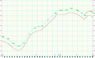
Click the Raise/Lower PVIs tool.

Specify your elevation change in the dialog box and click OK. Your new profile is now moved to your specified elevation.


You should right-click on the new profile and change its style under Profile Properties to differentiate it from the original visually.

Lastly, but most importantly, go back to the Profile Properties for your existing ground profile and switch the update mode back to dynamic.

If you forget to switch it back, changes to the existing ground surface will not be reflected in the the existing ground profile.


There you go! Have a great weekend!

Thursday, November 13, 2008

SQOTD: "Why Can't I Purge This Freaking Layer?"

In plain-old AutoCAD, several conditions will prevent you from purging a layer:

  • The layer has something on it
  • The layer is called 0 or Defpoints
  • The layer is current
  • It's a layer in an XREF drawing

Civil 3D takes the layer thing even further. If a layer (or linetype, or block, or text style, for that matter) is called by any style you can't purge it. It doesn't matter if the style is in use or not, you can't purge layers that are part of a style.

Soooo, if you *need* to kill the layer you can still do so. However, forcing a layer to die will cause the style that uses it send any labeling or object to layer 0. As a CAD purist, I can't advocate putting anything on 0 so be careful.

The (former?) Express command that will delete a layer regardless of the aforementioned limitations is LAYDEL .

LAYDEL will ask you to graphically select or pick layers by name. In either case it will ask you to verify that this is what you want to do. Any objects on those layers go bye-bye.

Happy purging!

Friday, November 07, 2008

Civil 3D Fall Down, Go Boom

FYI: Jason Hickey pretty much handed me this blog post on a silver platter. I can't take too much credit for the technical side of things.


So, one of my homies at a certain public transportation authority CC'd me on a problem she was having with Civil 3D crashing when she tried viewing the sheets created from the P&P process. When she tried opening the files we got "INTERNAL ERROR: !dbobji.cpp@6861: eNotOpenForWrite" and of course Civil 3D 2009 crashed out.


The main drawing contained some data references and an underlay of a V8 Microstation file. If she removed the underlay or converted it to a DWG first, no error.


Then she mentioned that Jason had her check the XLOADCTL system variable. For some reason this was set to 0 rather than the default.


I had her go to the Options dialog > Open and Save and set the Demand Load Xrefs setting to Enabled with Copy. (This is the same as setting the XLOADCTL to 2.)
Once we set that, all was well.
What that does is makes a super-secret, temporary copy of an XREFd drawing so that you can manipulate it and modify it in multiple places. The odd thing about this problem is that it wasn't happening for DWG Xrefs. But who am I to look a gift horse in the mouth?

Thursday, November 06, 2008

Support Question of the Day: Proposed Profile After The Fact

Oh to be a full-time blogger. But then again, I wouldn't have the client interactions which keep me on my toes and inspire me to blog.


I've got a bunch of posts in progress but the following is a quickie that had me slack jaw for a few minutes.


Q: What happens if you create P&P sheets based off of an existing ground profile and want to add the proposed profile after the fact?


A: If you are creating P&P sheets in a separate drawing (which you ARE, AREN'T you???) and relying on the automatically created data references to pull data to your new drawing, any new profiles created will not automatically get added to the new drawing.


You have two options:

1) Recreate the sheets. (Which is a sucky option if you've gone and annotated and/or tweaked the P&P sheets.)

2) Manually create a data shortcut to the proposed profile.


  1. In your main drawing, change your Prospector to Master View.

  2. Find the Data Shortcuts area and right-click.

  3. Select New Data Shortcuts Folder.

  4. Create a folder for the data shortcut.

  5. Right-click again and pick Create Data Shortcuts.

  6. Put a check mark in the box for your proposed profile. Civil 3D will automatically grab the alignment too. That's normal.

  7. Jump to your P&P sheet drawing.

  8. In Prospector, browse to your data shortcuts.

  9. Locate the design profile, right-click and select Create Reference

  10. Repeat steps 7-9 for any additional P&P sheet drawing files.

Once the data shortcut has been made, updates will show up in the P&P sheet files as normal.

Civil Engineers Don't Make the News Much...

But when we do, isn't it comforting to know that the Los Angeles signal system is computer controlled?

More to come today.

Friday, October 24, 2008

Product Review: Data Reduction for Civil 3D by Eagle Point

The Cost:
  • $795 per seat stand alone license / $945 on a network license
My Favorite Aspects:

  • Super-easy linework.
  • Ability to reprocess points through Description Keys.
  • Downloads, converts formats and pulls in survey data directly from collector in 1 step.
  • Forces people to get description keys in order.
  • Super-easy linework.

I'm lukewarm about:

  • Data Reduction bypasses Survey Database and Figure generation altogether. (But don't we all agree that Survey Database and Figures have some clunkiness to them?)
  • Forces people to get description keys in order. (yes, this is both positive and negative).
  • It is an add-on. Add-ons tend to be a few months behind on release cycle from Autodesk products.
  • Price. If you've got Civil 3D you've already spent some serious coin.
The Details:

Full disclosure statement - I still party with the kids at Eagle Point whenever I get a chance. If you ever get the opportunity, I highly recommend it. They will be at AU this year, make them buy you beer. Tell them Lou sent you.

After a little begging, eyelash batting and/or ear licking, my buddy, Steve B., sent me the release version of Data Reduction for Civil 3D a day before the official release. I am running this on a 64-bit Vista Business laptop with 4 gig ram. The overhead to run Data Reduction is negligible compared to Civil 3D 2009 so my specs are pretty much a non-issue.


In a nutshell, Data Reduction contains the tools that I expected Civil 3D to have from the get-go. From a single pull-down menu a user can download directly from most data collectors (via your com ports) and into Civil 3D 2009. It has a much more seamless feel than Survey Link.


Data Reduction can import the points, add them to a point group (an existing one or one you make on the fly), and create a surface for you in one complete step. Bellisimo!


Data Reduction leverages your description key sets to process points. It's strength is the ease with which you can create survey linework. Users have the choice of using the Description Key as the line name or using the linework designators in a point's description to produce linework.


Personally, my preference is to use Description Keys as the line name, but for folks who are very comfortable with a traditional Eagle Point workflow, they can use fully customizable designators to set up lines. Data reduction places cogo points and polylines in your drawing (not survey points and figures).


For Eagle Point users the workflow is comfortable and logical. For folks who have never used it before, there is one more step you may not expect before you see the fruits of your labor. After the file is downloaded or imported, you need to reduce. The beautiful thing about this is if you forget to set something up in your Description Key Set, re-reducing the job wipes your slate clean and reprocesses your point data.


In closing, I'd say that the Data Reduction gets an A from me. Anyone using Civil 3D 2009 and has surveyors that are a little skeptical will benefit from this product. Try it out, and don't forget to tell them Lou sent you!


Wednesday, October 15, 2008

Coming Soon!

AUGI Chicago was great. Met some really great folks down there, including Andy Parr who is one cool mo-fo civil application engineer. As soon as I get a chance to do so I would like to buy that fellow a few beers.

Here are few topics that I am planning on writing about as soon as I get some time:

  • How to start embracing the ribbon panels with open arms - yes even in Civil 3D.
  • The user-suggested trick of having multiple sets of pipe rules to force different things to happen during design iterations (such as matching inverts).
  • More survey stuff in Map.
  • My review of Eagle Point's product Data Reduction.

Stay tuned.

Thursday, October 09, 2008

Part Builder

Louisa,

I was wonder if you knew of a good book or resource for Civil 3D Part Builder ?

Cheers,
CD

Hi CD -

Generally when people ask about part builder my advice is generally, "Run. Run away. Run screaming." If there is a specific structure you are looking for that doesn't exist in the default library I usually recommend is using a null structure and snapping a block where you need it.

However, if you are feeling a touch masochistic and have time on your hands - part builder is just the thing for you.

There's no part-builder specific books out there, just a hodge-podge of information put together by Autodesk and a few users. Part builder originated in the MEP (mechanical, electrical and plumbing) side of Autodesk so when you crack it open there are very few indicators that you are building a civil thing. Additionally, even though you think you are in AutoCAD, the minute you are in part builder all your CAD knowledge is useless. Part builder does not recognize autocad lines, arcs, circles etc and needs you to do all the drawing from the part builder interface.

Step 1: Watch this video https://www120.livemeeting.com/cc/autodesklearning/view?id=BSD10-19&pw=AudienceThis was the most helpful to me. It was put together for the MEP side of Autodesk software, but it will give you an idea on how the interface is put together.

Step 2: Read chapters 26 and 27 in the Civil 3D users guide. If you installed civil 3d in the default location, it is located in c:\Program Files\AutoCAD Civil 3d 200X\Help\Civil_UG.pdf. Just read this for the terminology and the tips. Don't bother running through the example because it makes no sense.

Step 3: Download the part builder pdfs from Civil3d.com (you may have to sign up for their website to do so - it's worth your time)
http://www.civil3d.com/wp-content/uploads/2007/08/vault-5106-la-with-top-5106-tl3-332.pdf
http://www.civil3d.com/wp-content/uploads/2007/09/no233a.PDF

Step 4: Cross your fingers and go for it. Try not to pull out too much hair!

Good luck and hope this helps! -Lou

Monday, September 29, 2008

Civil 3D and Layers

When I teach Civil 3D, I like to get people in the habit of using Styles to control display of surfaces and points. Some objects, such as corridors, are displayed based on a few different styles and it's just plain quicker to use layers to turn it on or off.

When it comes to point display, leverage your Point Groups. One of my favorite tricks with point groups is manipulating their display order. If you understand point groups, you know that a point can belong to more than one group. For instance, you might have a benchmark point that is part of a "Control Points" group and is also part of a "Surface Data" group. Additionally, whether you like it or not, the point is automatically part of _All Points.


So, what the heck? How does civil 3D know what style to apply to the point?


In my example here, I'm going to hijack _All Points as my no display group. In other words, I just jumped into the properties of _All Points and set Point Style and Label Style to "None".


Next, I went to the Overrides tab to make sure that points that are controlled by description keys for styles also follow this group. I toggled on Point Style and Point Label Style.

Now that I have a "no display" group set up I need to reorder the groups.

The style the point takes all depends on the order of the point groups as displayed in Properties.


Right-click on Point Groups and select Properties.


You will see the listing of your point groups. From the top down, the order in which the group shows up in here is what determines what style takes over. Use the blue arrows to move a group up or down and manipulate this listing. In this case, with _All Points at the top of the listing, no points will be visible. If I wanted just Utilities points to show, I would bump the Utilities group above _All Points.


When it comes to Surfaces, changing the display is something you will end up doing constantly through the design process. To turn a surface "off" use the style! If you have started a project from one of the default templates, you already have a Surface Style called "_No Display." Right-click on the name of the surface in Prospector and hit Properties. (You can also left-click, then right-click the surface graphically to get into Surface Properties, but for pure newbies I stick to prospector - less confusing.)

In the information tab set your surface style to _No Display and click OK.


Thursday, September 18, 2008

SQOTD: That Wagon Wheel Looking Thing in My Drawing


If you have a coordinate system turned on in Civil 3D 2009 or Map 2009 you will see this goofy-looking symbol in your drawing. It can't be selected and can't be deleted but you can just turn it off.


At the cad command line, type GEOMARKERVISIBILITY hit enter, then set the value to 0.


Goodbye wagon-wheel thingy.


Wednesday, September 17, 2008

YES! Floridians are Smart!

Taking after my buddies at WisDOT, Florida DOT has chosen Civil 3D as their design package.
Two down, 50 to go! (I'm counting Guam and Puerto Rico DOTs too)

Check it out on Yahoo biz!
http://biz.yahoo.com/prnews/080917/sf33494.html?.v=1

Monday, September 15, 2008

A Snippet of my Corridor Paper

I'm kind of digging these graphics I made for the AUGI CAD camp in Chicago. Here's a little preview of the paper I'm putting together.


"This scematic is what our cross section might look like in a fill situation. Our original 12’ lane has been overridden by the location of the EOP alignments. Because this example does not use a Profile target, the final elevations of the EOPs are controlled by the slope from the assembly. "


"When building a corridor surface, you will most frequently use Links to add data. Each Link has at least one name that Civil 3D uses to group like objects. For instance, when creating a daylight surface, you would add Top links to the surface. If you want a surface from the bottom-most level of your subassembly, you would choose Datum links. In the figure above, notice that links can have more than one name. "

Thursday, September 04, 2008

Create a Profile without a Surface

I’ve run into several people who have point data that exists along a single line and wish to see profile data. With no point data outside this string of points it is impossible to create a surface model. Without a surface model it is not as easy to create a profile.

There’s a little known trick a person can perform in order to create a profile from a set of points. It involves using the 3DPOLY command, transparent commands and LandXML. The attached PDF explains in detail what is needed to create an existing profile from linear points.

Here is the PDF: Profile with No Surface

Here is the TXT file you can download for practice. trail.txt

Friday, August 29, 2008

Busy fo' Shizzle

The weeks leading up to vacation were so mellow, I got spoiled. Seems like 10million things have been hitting all at once. I'm training a really cool group of guys in Chicago how to make pretty surfaces in Civil 3D. They are awesome, quick learners and total smart-asses - MY FAVORITE!

I'm just finished training some government employees base ACAD in preparation for a move to Civil 3D. That went well, but I find it difficult to teach base Autocad these days. I totally forget that you have to actually be taught how to make a new layer. Civil 3D has me spoiled. And panning and zooming with the mouse? To me it is part of my repertoire of involuntary movements like breathing or making a martini. Others have to be shown, I guess. Weird.

In other news, I'm teaching at AUGI CAD Camp on October 14th in Chicago. Totally STOKED! I'll be doing two classes, "Corridors 101: Assemblies, Targets and Frequencies Exposed!" and "No Voodoo Required – Data Shortcuts and X-Refs with Cross-Section Sheets." Robert Green will be there. Hopefully he's up for autographing my CAD Managers book.

Speaking of October, we also have some user groups happening in Wisconsin. I'll be presenting my little paper on how to export data between Eagle Point and Civil 3D, and esteemed colleague Russ will talking about cross sections.

In Madison:
Thurs. October 2nd
11:30am - 1:30pm
Quality Inn & Suites
2969 Cahill Main
Fitchburg, WI


In Milwaukee:
Thurs. October 9th
11:30am - 1:30pm
MasterGraphics - Waukesha

Register by going here: http://www.masterg.com/events/civil-infrastructure-events

Hope to see you at one of the many events around the midwest!

Tuesday, August 19, 2008

I'm Back!

Had a great vay-cay.
Want to see all my photos? Go here: http://picasaweb.google.com/surpriseladylou/Prague2008

However, here is an interesting tidbit:

Does this logo
look familiar to anyone?

Wednesday, July 30, 2008

Eagle Point to Civil 3D

This might end up being my last post before I head off on holiday next week - but then again I've got a 9+ hour flight on which I might end up creating all kinds of content.

Enjoy the following document which describes how to export a LandXML file from Eagle Point and what to do with it once it is in Civil 3D.

Exporting from Eagle Point into Civil 3D Using LandXML

Peace out.

Monday, July 28, 2008

Base AutoCAD Information

The following information applies to base Autocad 2009 users only. However, whenever there are changes to base Autocad, the updates make their way into Civil 3D more often than not.

AutoCAD 2009 Subscription Tools

Autodesk has released a Bonus Pack filled with goodies from the AUGI wishlist. These enhancements and goodies are available to current subscription customers using base AutoCAD 2009.

So what’s in it?

  • Consolidated Inquiry tools. With one command, MEASUREGEOM, you can get distance, area, volume, angle or radius.

  • Additional tools in PEDIT and SPLINEDIT. You now can convert a spline to a polyline and reverse the direction of a polyline with this tool.

  • Rotate a Viewport and View together. There is a new system variable, VPROTATEASSOC. When the variable is set to 1, rotating the viewport brings the view with it.

  • Updates to PURGE command. You can use the new tool to purge empty text boxes and zero-length geometry.

Download them from the Autodesk Subscription Center. Login is required. If you are not sure how to log in, contact your CAD manager or I.T. contact to see if a subscription account has been set up for you.

Base AutoCAD 2009 Service Pack

Autodesk has released the first product update (service pack) for the AutoCAD 2009 and AutoCAD LT 2009 products. Updates have been made in the following feature areas:

  • 3D Visual Styles

  • Annotation Scaling

  • External References (xref) palette

  • Raster Images

  • Partial Open

  • Plot

  • Properties Palette

  • Hatch

  • Remote text (rtext)

This update includes a wide range of general updates, including fixes to Attributes, Blocks, Hatch Boundaries, and many other functional areas. In total, more than 100 improvements are included in this product update.

Anyone can download this update from Autodesk’s website.

Friday, July 18, 2008

A Good Friday Photo

A photo of my co-workers from techcamp.
They were definitely taking charge...of the free beer.

Wednesday, July 16, 2008

Ceci N'est Pas Une Pipe

Translation: This is not a pipe.

It is a parametric part meant to represent a concrete arched culvert as described by ASTM 506.


Click the image above to download the files.
This part is created for Civil 3D 2009 only.

Download the zip file (less than 300k) and extract it to your US Imperial Pipes directory. It will create a folder called Arched Pipe containing the files needed to use this part.

XP Path: C:\Documents and Settings\All Users\Application Data\Autodesk\C3D 2009\enu\Pipes Catalog\US Imperial Pipes

Vista path: C:\ProgramData\Autodesk\C3D 2009\enu\Pipes Catalog\US Imperial Pipes

Once the part is extracted to the correct location, type PARTCATALOGREGEN at the command line. Then type P for pipe. Once that is complete, you can add the part to your parts list.

To add to your parts list, go to the Pipes menu > Parts List >Edit


Pick the list you wish to modify and click the Edit Current Selection option (even though you will be tempted to click OK at this point, don't!)


Get yourself to the Pipes tab and right-click the list name. Select Add part family...


This pipe should show up under the Arched Pipe category. Put a checkmark in the box and click OK.


If you do not see the pipe, verify that the files you unzipped went to the correct folder.


Now that you have the pipe category listed, right click on it and select Add part size...


Toggle Add all sizes and set any hydrolic constants you may want. Click OK.


Set your pipe styles, rules and render materials as desired. Click OK.


Click OK to get back to your drawing and use the new pipe to your heart's content.


Here is a table showing the size requirements for these parts, per ASTM 506.


If you have problems with this arched pipe, let me know.

Tuesday, July 08, 2008

Raster Design 2009 + Civil 3D 2009

You'll want to download this hot-fix if you have any Autocad 2009-based product plus Raster Design 2009. You do not need this if you have the Raster Design 2009 Object Enabler only.

In Civil 3D, you may notice that items do not hatch themselves as expected.

The first image shows what my solid-filled slope arrows look like before the fix. The second image shows the slope arrows after the fix. (You may see this rear its head in other styles or objects as well. This is where I noticed it first.)


To apply the hot-fix, download the zip file and extract it to a temporary location. One of your extracted files is AeciGix51.dll for 32 bit installation (not sure which is which? Check the file properties).

Exit Civil 3D. Using plain-old Windows explorer, find the Raster Design 2009 directory. This will most likely be c:\Program Files\Raster Design 2009. There already is a AeciGix.dll in there, so rename it to AeciGix-old.dll. Drag the new one into this directory. Restart Civil 3D and objects should fill-in as usual.

On a not-very-closely-related note: There is a known problem with slope arrows not picking up any other color scheme besides Blues. It's will not harm the actual information, its more of a nuisance than anything.

Thursday, July 03, 2008

An Experiment in E-commerce


Hi All-

As many of you know, I enjoy writing documentation and helping spread the good cheer when it comes to Civil 3D. I've written a document for an introduction to interesection design and want to share it. However, I put a lot of personal time and effort into it - therefore I am going to try a little experiment. Are people willing to spend money on the information I give them? We'll see...


Civil 3D 2009 Intersection Design 101 - $5.99USD (Quite a bargain for the folks using Euros!)

This document is intended for people who already have built Civil 3D corridors and want to take their knowledge to the next level. Concepts also apply to Civil 3D 2008. This 18-page PDF document will introduce you to the basic concepts behind interestion design.

To get the most out of this paper:


  • You have a basic understanding of corridor design.

  • You understand how to create and modify both Alignments and Profiles.

  • You understand how to build assemblies.

  • You can perform some minor style modifications.

In this example we will create a very basic intersection:


  • Aspen Lane and Maple Road have same cross section.

  • Both streets maintain crown through the intersection.

  • The streets are perpendicular to each other.

  • The radii of the curbs are equal.

Click on the button below to purchase the PDF document I created for intersection design.

Tuesday, July 01, 2008

Let's Make the Most of This Beautiful Day

Ms. Holland's Neighborhood, Civil 3D style:


This little subdivision only exists in my mind and as a 3D model on my computer. This rendering took 4.3 hours in Civil 3D 2009 on an HP with Intel Core2 2 GHz Duo, 4 gig ram and Vista 64.


The numerous 3D trees took forever to render. These are the concept trees found in the Civil MV Blocks palette.

Some settings I had on:
  • Fog - Off
  • Fog Background - Off
  • Sun - On
  • Sky - Off
  • Force two-sided - ON (which is needed to render the corridor correctly)
  • Output size - 2048x1536
Click on the image for full-blown effect. Can you spot the 3 pedestrians? Hint: 2 are on the nature trail and one is on the sidewalk.


Monday, June 30, 2008

Smack My Map Up

I've yet to run into a program that I couldn't install on 64-bit Vista. The latest challenge I've taken on is Map 3D 2009.

Disclaimer: If you attempt the following procedure, you are on your own. Autodesk will not support these "hacked" versions. I am just putting this out there for your information - I assume no responsibility for this not working for you, your lost time or hair.

This is how I beat Map3D 09 into submission:

  1. Download Orca.msi.
  2. Copy the Contents of the Map DVD to a hard drive (you can delete this after the install is complete).
  3. Browse to the (x86) folder and open ACADMAP.msi with Orca. (After Orca is installed you should be able to right-click on this and select Edit with Orca.)
  4. There are three locations to delete in this MSI file. Table: Custom Action Action: Checkfor64bitOS, Table: InstallExecuteSequence Action: Checkfor64bitOS and Table: LaunchCondition Condition: VersionNT >= 500 AND NOT VersionNT64.
  5. Save and close the modified MSI file.
  6. Run the install by double-clicking the MSI file. I recommend installing to default locations.
  7. Lastly, we have to move some resources that were placed in the wrong location. Browse to C:\Program Files\Autocad Map3D 2009 and move the entire folder to the C:\Program Files (x86) directory.
  8. Click YES to merge folders if it asks.

You should be good to go from there.

Friday, June 27, 2008

Doing a Little Remodeling

I just added Google analytics to my blogs and decided to use the opportunity to freshen up the look of things. Feel free to comment on the new layout.

Thursday, June 26, 2008

Profile Style Weirdness


I have so much on my mind this week, I'm so glad I finally have some time to blog.


This first post is regarding a funny "gotcha" in the profile styles.


It all started when I was doing some one-on-one training on P&P sheets for a client and he wanted all of his profile views to have a vertical exaggeration of 5x, rather than the default found in the OOTB templates of 10x.


To change this I went to the profile view style by right-clicking on the view.


I jumped to the Graph tab and set the vertical exaggeration to 5 and thought I was home free. In theory, I'm changing the style that is active for all the profiles. The funny thing was that all the profiles changed except for the one I had right-clicked on.


After tinkering and repressing my curse reflex in front of a client I discovered that even though the profile in question was not being split, it was grabbing the style as if it were.


To fix it, I went to the Profile View Properties and unchecked the Split Profile View option.

A different way to solve it, if you are always going to have a 5x exaggeration anyway is to change all of your styles to be the scale you want. Just make sure to go into them via the Settings tab - 'cuz right-clicking the object won't get you to the correct style!


The same info applies to both 2008 and 2009 Civil 3D. Hope this saves someone some grief.