Level of Difficulty: ![]()
In this post we are going to import a text file into Civil 3D. The following is an excerpt from this file.
1,5477.4814,3886.3451,122.9931,BM001
2,5554.5536,4234.3339,107.7749,IPF
3,5528.4406,3804.3077,129.1600,FENCE
4,5523.5055,3795.4675,129.3400,FENCE
5,5522.0336,3787.1183,129.2100,FENCE
The file is a simple Point Number, Northing, Easting, Elevation, and Descriptions file, commonly referred to as an ASCII file.
1) First, go to File > New in Civil 3D.
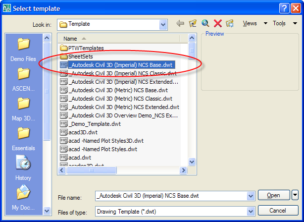
2) Select the Template file called _Autodesk Civil 3D (Imperial)NCS Base.dwt
3) Click Open
We are starting a new drawing with a template that will contain all the needed styles for this exercise.
4) On the Prospector Tab, find Points
5) Right-click on points and select Create…

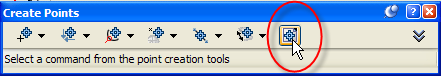
6) Click the Import Points icon.
7) Verify that the format is set to PNDEZD (comma delimited)
8) Browse for the source file.
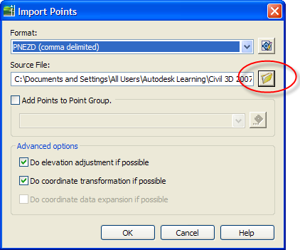
9) Click OK
10) Zoom Extents to see the newly imported points.
Next we are going to change the look of these points, and add labels.
1) In Prospector, locate Point Groups
2) Click the plus sign
 next to Point Groups to expand the category.
3) Right Click on the _All Points group
4) Select Properties
5) Change the Point Style to Standard by using the drop-down
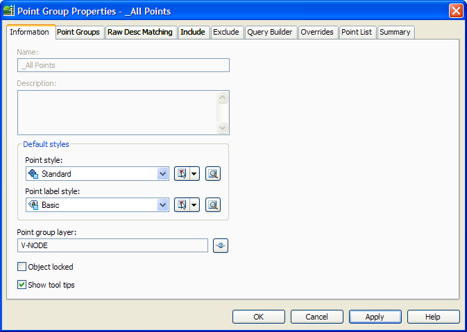
6) Change the Point Label style to Basic
7) Click OK
At this point you should see points on the screen with a simple X symbol and labels showing point number, Elevation and Description.
8) Save the file as new-topo.dwg in the same directory as the text file.
Now, to make the text around our points a little smaller we are going to change the scale of the drawing.
9) In the Settings Tab, right-click the name of the drawing and select Edit Drawing Settings…
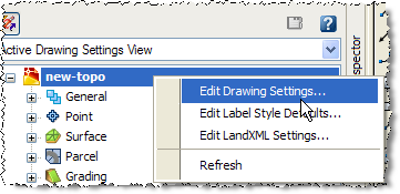
10) On the Units and Zone Tab, change the scale to 1” = 20’

11) Click OK
The text should now be smaller.
12) Save the drawing!
Great Job.