When I teach Civil 3D, I like to get people in the habit of using Styles to control display of surfaces and points. Some objects, such as corridors, are displayed based on a few different styles and it's just plain quicker to use layers to turn it on or off.
When it comes to point display, leverage your Point Groups. One of my favorite tricks with point groups is manipulating their display order. If you understand point groups, you know that a point can belong to more than one group. For instance, you might have a benchmark point that is part of a "Control Points" group and is also part of a "Surface Data" group. Additionally, whether you like it or not, the point is automatically part of _All Points.
So, what the heck? How does civil 3D know what style to apply to the point?
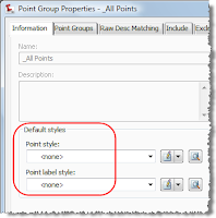

In my example here, I'm going to hijack _All Points as my no display group. In other words, I just jumped into the properties of _All Points and set Point Style and Label Style to "None".

Next, I went to the Overrides tab to make sure that points that are controlled by description keys for styles also follow this group. I toggled on Point Style and Point Label Style.
Now that I have a "no display" group set up I need to reorder the groups.
The style the point takes all depends on the order 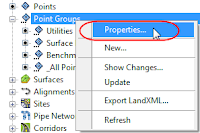 of the point groups as displayed in Properties.
 of the point groups as displayed in Properties.
Right-click on Point Groups and select Properties.

You will see the listing of your point groups. From the top down, the order in which the group shows up in here is what determines what style takes over. Use the blue arrows to move a group up or down and manipulate this listing. In this case, with _All Points at the top of the listing, no points will be visible. If I wanted just Utilities points to show, I would bump the Utilities group above _All Points.
When it comes to Surfaces, changing the display is something you will end up doing constantly through the design process. To turn a surface "off" use the style! If you have started a project from one of the default templates, you already have a Surface Style called "_No Display." Right-click on the name of the surface in Prospector and hit Properties. (You can also left-click, then right-click the surface graphically to get into Surface Properties, but for pure newbies I stick to prospector - less confusing.)
 In the information tab set your surface style to _No Display and click OK.


