Friday, August 31, 2007

Little Tidbit of Love for the Weekend

Find Sheetset Manager Annoying?

Turn it off by changing SSMAUTOOPEN and SSLOCATE variables to zero.

I am working on a lovely little whitepaper on Sheetsets for Civil3D Users. I promise I'll post it eventually. This nugget was found during the research process.

Have a grrrreat weekend.

Wednesday, August 22, 2007

Mark your calendar!

September AutoCAD Civil 3D User Group Dates:

Thursday, September 6th, 2007
11:30 a.m. - 1:00 p.m.
At The Quality Inn & Suites - Madison

2969 Cahill Main
Madison, WI 53711

OR

Thursday, September 13th, 2007
11:30 a.m. - 1:00 p.m.
At MasterGraphics - Waukesha

20633 Watertown Ct., Ste 100
Waukesha, WI 53186

Tuesday, August 14, 2007

SQOTD: Changing Alignment Stationing


QUESTION:

In C3D, I have an alignment for a road in a park that creates a closed

loop. When I turn the polyline into an alignment, it seems to randomly

select the starting point for the alignment. I want to change the

default location it is choosing for the beginning of the alignment - in

alignment properties I see that I can modify the reference points

stationing, but it won't allow me to change the stationing for the

starting point of the alignment. How can I do this?

ANSWER:

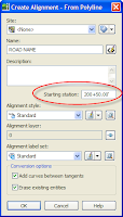
When you are first converting a polyline into an Alignment, the end nearest to which you click becomes the 0+00 station. (In the case of a closed loop, the vertex closest to where you pick becomes 0+00) If you don't want it to be 0+00 you can set it on the same window where you give it a name.


BUT if you forget you can still change it.

If you just want to flip-flop the

alignment end-to-end you can go up to the Alignments menu and select Reverse Alignment Direction.

If you want to change the start station of the alignment to be

something other than 0+00, jump into the Alignment properties.

Left-click, then right-click on the Alignment (or right-click on

its name in Prospector)and select Alignment Properties. Go to the Station Control tab.


First, type in the Station where you really want it to start. Second, click the pick-in-cad button next to the X and Y cords.

Civil 3D will throw a warning message at you telling you that you are about to wipe out any station equations you might have entered and anything referencing that alignment will need to be updated. Just say OK and it should pop you into CAD with a special station-picker tool. Use your object snaps to re-snap to the beginning of the alignment, then hit enter. Back at the Alignment properties window, click Apply and you should see your station information update.

And that’s it!

Let me know how it goes.

Louisa


Monday, August 13, 2007

AU - Good as Gold

www.autodeskevents.com/au2007


You should find a way to attend this event. I'm ecstatic that I get to go this year. The training you get is second to none. The instructors are the best in the field.

AU is being held at the Venetian in Las Vegas November 27th – 29th.

Autodesk University Full Conference Pass is $1645. After Oct. 5 the price goes up to $2,145


Check with your reseller for discounts. HINT, HINT.

Early registration starts: Wednesday, August 15

General registration open: Wednesday, August 22

See you there!

Friday, August 03, 2007

Troubleshooting Cul-de-Sacs

Did you know that in French, the literal meaning of cul-de-sac is "bottom of the bag." Did you also know that "cul-de-sac" is Quebecois slang for the seat of your pants? I'm not making that up - some clients in Montreal told me that.

So. Civil 3D can make great cul-de-sacs if you know what you are doing. This post does not teach you how to make them, rather I'd like to discuss some common things that can go wrong.

Situation #1: The Cone to China

This is what it looks like in plan view with contours turned on. In my designs, I like to whip the alignment around 180 degrees (to avoid situations 2 and 3).

So the glob of contours is happening right where my north EOP (Edge of Pavement) alignment is supposed to touch my south EOP alignment.


And this second picture is what is going on with the surface model in the Object viewer. YUCK.

Why does this happen? Stationing somewhere is not perfect. Your profiles' stations must end EXACTLY at your alignments' end stations for the EOP's. Also the EOP's must meet exactly with not so much as a hairline gap.


Situation #2: The Gap

It not just a place for mediocre pants anymore.

In object viewer you may be lulled into a false sense of security with this one. At first glance, the surface model looks just fine.

What has happened in this situation is the end of alignment is not centered exactly inside the circular portion of the cul-de-sac.

In this case, it is slightly inside of the angled segment of the alignment. The corridor parameters tell the assembly to look for the main centerline as a width target. The base line is the EOP. When assemblies get applied at each frequency line, they shoot out perpendicularly to find their target. If the target alignment is out of whack, the assemblies miss the target and give up. The width they actually are is how the assembly was drawn- no stretching happens.

Situation #3: Don't Be Too Obtuse

In this situation we see the same cul-de-sac, except the off-center end of the alignment is slightly outside the angle of the alignment.
The assemblies overshoot the Alignment endpoint they should be hitting, and reconnect with their target in the wrong spot.


The lesson you should take away, here, is that corridors only do what they are told. You need to make sure your stations line up on your baseline's alignment and profile. You need to make sure the endpoint of the alignment is exactly in the center (unless you use my world-famous button-hook method - blogging soon). Too long or too short of a target alignment will give you problems and, as shown above, left or right of the center of the cul-de-sac will also goof you up.

Good luck!