Showing posts with label two-star. Show all posts

Friday, November 21, 2008

Expression Example

Expressions are one of those tools that you never know how you might use them until you need them.
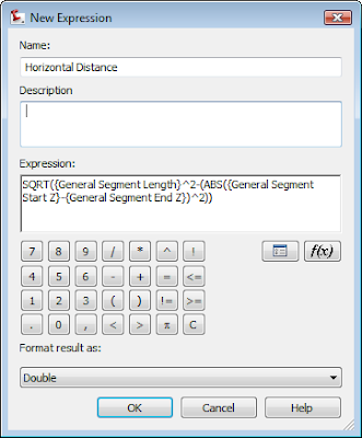
Yesterday I found myself wanting to check to make sure some figures I created were truly at elevation. I wanted to see both the slope distance and the horizontal distance in the label. However, horizontal distance is not an option in the native list of components.

I created this expression under Settings > General > Label Styles > Line.


Right-click on the Expressions and select New. You'll see the dialog at left.

Here's the "math" that you can use to copy and paste into your expression window:


SQRT({General Segment Length}^2-(ABS({General Segment Start Z}-{General Segment End Z})^2))


Once the expression was created I made a copy of the style Bearing Over distance by right-clicking and selecting Copy. On the copy, I right-clicked and selected Edit. On the Information tab, I renamed the style to "Bearing over Distance (Horiz Dist)". On the Layout tab, I set my active component to Distance, and gave the component name a quick rename.


Then I clicked the ellipsis to get into the text component editor.


Your expression should now show up in the list of available Properties. Select Horizontal Distance, set precision and how you'd like the number to show up - then click the blue arrow to add it to the right side of the box.

Once you click OK, OK, and complete the label you can use it on lines, polylines, figures and feature lines.

However, it does not work on Alignments, Parcel Segments or 3D polylines.


Monday, September 10, 2007

SQOTD: Two Common Questions

Q1: Why Can't I Find all My Style Settings?

A1: In the settings tab there are now multiple ways to "sort" the list of items.

If you want to see it all, change the settings drop down to Active Drawing Settings View.

Master View Shows you everything from all open drawings. You'd need this set to Master View to check things in and out of Vault. For people who don't use Vault - Master View is a tad confusing.
Active Drawing Labels Only is a subset of Active Drawing Settings View, minus things like Code and Marker Styles and Corridor Styles. Basically, this view omits all object styles.

Labels Only View will show omit object styles, and it will show you label styles for all open drawings. Kinda weird.

Long story short: You probably want to be in Active Drawing Settings View.

Q2: How can I turn off frequency lines without turning off the rest of the corridor lines?


A2: First, jump into your corridor properties and figure out what Code Set Style you are currently using. In this case, All Codes. Make a copy of All Codes and call it NO SHOW or something like that.


We will also need a _No Marker style and a _NO SHOW LINK Style.


In the Code Set Style dialog box, set all the link styles to the _No Show Link. Set all the Point styles to _No Markers.

Click OK a couple of times and your frequency lines should be hidden.

To get them back, just change the code set style.

Not bad.

Thursday, July 05, 2007

Thing that Does More than Meets the Eye


No, its not a transformer, it's a subassembly. Well, I guess in a way a subassembly IS a transformer of sorts, but that's another post.

So, I was so confused the other day when I didn't see Crown_Sub code listed in my Corridor Properties under Codes.

Turns out I had to turn Crown Point on Inside to YES before they show up. Once you have that turned on, you can go into your code set style and slap a label on that bad boy. That way you could label elevation of the base at zero offset.
Kooky.

If you go into the Help file to check out your coding diagram, some items say they are optional.

I guess its not that hard, but I'd reword this option as "Show Optional Codes" or something. But that's just me. I ride the short bus to the office.

Tuesday, July 03, 2007

This Means Something


Yeah. I know what it means...it means I have WAY too much time on my hands.

Well, it is a holiday week and the phones are pretty quiet. Also I took two PSE's (Partner Service Exams) yesterday and my brain is feeling a little mushy.

So, I thought I'd share with you my Devil's Tower, WY surface, rendered with...you guessed it...mashed potatoes.


First I found Devil's Tower in Google Earth. I zoomed in nice and close - Google "Eye Altitude" of 7000'. Then, in Civil 3D I set my coordinate system to Wyoming Eastern State Plane WY83-EF, because hey- if you're gunna F-around you might as well do so accurately as possible.

So then I use the schnifty import Google Earth Image and Surface... command.

I was a little disappointed with the DEM resolution of the tower itself.


Armed with some factoids, photos and memory of having been there twice I "guesterpolated" (copywright 2007, Louisa Holland) the rest.

I sketched in some additional contours and added them to the surface.

Now my last step was to whip up a render material. Get it? Whip up?


I found a photo of mashed potatoes through Google images and used it to create a render material. Because the tower is so large and the potato image was so small I had to increase the size of my mashed potatoes by 500x.

Then in the Surface properties, I applied the render material to my tower.

When I get time, I might take this into Viz to make the potatoes more fluffy. Until then this is all I got.