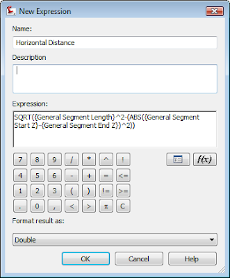
Yesterday I found myself wanting to check to make sure some figures I created were truly at elevation. I wanted to see both the slope distance and the horizontal distance in the label. However, horizontal distance is not an option in the native list of components.
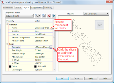
 Once the expression was created I made a copy of the style Bearing Over distance by right-clicking and selecting Copy. On the copy, I right-clicked and selected Edit. On the Information tab, I renamed the style to "Bearing over Distance (Horiz Dist)". On the Layout tab, I set my active component to Distance, and gave the component name a quick rename.
 Then I clicked the ellipsis to get into the text component editor.
Your expression should now show up  in the list of available Properties. Select Horizontal Distance, set precision and how you'd like the number to show up - then click the blue arrow to add it to the right side of the box.
Once you click OK, OK, and complete the label you can use it on lines, polylines, figures and feature lines.
However, it does not work on Alignments, Parcel Segments or 3D polylines.


