Monday, November 24, 2008

SQOTD: Resolving Multiple XREFS

Q - Is there a lisp program available to redirect the saved path for xrefs when the directory changes on the network? (e.g. xrefs once located in N:\Drawings\Building\ are now found in P:\Eng\Shared\Drawings\). Looking for a better way than to doing them all manually for every drawing that gets opened.


A - There's an even better way than using a LISP routine.

There is a little-known utility that has come with AutoCAD for years that will do just what you are looking for. Look for a file named ADREFMAN.exe. This should be located in your AutoCAD folder: C:\Program Files\AutoCAD Civil 3D 200X\
[If you can't find AdRefMan.exe, look on your install DVD.]

When the manager is open, click Add Drawings. Browse to the folder where your drawings are now stored and select as many as you need.


Next, AutoCAD will ask you if you want to "Add Xrefs regardless of nesting level" or "Add only first level Xrefs". Most people should choose Add only first level Xrefs.

The manager will show you any DWG's, Images, Plot Styles or Fonts it thinks you need.

On the right hand side of the box, expand By Reference and highlight the XREFS to narrow down the listing.
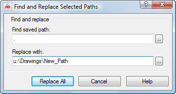
Using your shift key, multi-select the unresolved XREF drawings on the right. Click Find and Replace .

Replace the old path with the new, then click Replace All.
[In this example, all of my path types were set to Relative when I created the references, therefore I am seeing just a period (.) instead of a full path for my saved path.]


Click Apply Changes at the top of the window to save the results.
You should be ready to keep working!

Friday, November 21, 2008

Expression Example

Expressions are one of those tools that you never know how you might use them until you need them.
Yesterday I found myself wanting to check to make sure some figures I created were truly at elevation. I wanted to see both the slope distance and the horizontal distance in the label. However, horizontal distance is not an option in the native list of components.

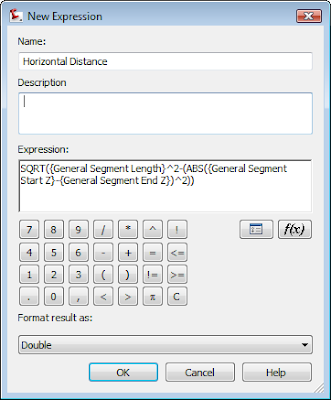
I created this expression under Settings > General > Label Styles > Line.


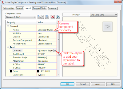
Right-click on the Expressions and select New. You'll see the dialog at left.

Here's the "math" that you can use to copy and paste into your expression window:


SQRT({General Segment Length}^2-(ABS({General Segment Start Z}-{General Segment End Z})^2))


Once the expression was created I made a copy of the style Bearing Over distance by right-clicking and selecting Copy. On the copy, I right-clicked and selected Edit. On the Information tab, I renamed the style to "Bearing over Distance (Horiz Dist)". On the Layout tab, I set my active component to Distance, and gave the component name a quick rename.


Then I clicked the ellipsis to get into the text component editor.


Your expression should now show up in the list of available Properties. Select Horizontal Distance, set precision and how you'd like the number to show up - then click the blue arrow to add it to the right side of the box.

Once you click OK, OK, and complete the label you can use it on lines, polylines, figures and feature lines.

However, it does not work on Alignments, Parcel Segments or 3D polylines.


Friday, November 14, 2008

SQOTD: How to Make a Copy of Your EG Profile


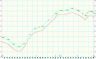
Q. I was wondering if there is a way in Civil 3D 2009 to make a copy of my existing ground profile 4 feet down from the original in order to show a location for my water line.


I tried to copy my existing profile but the whole toolbar is greyed out when I try to edit geometry.

A. Select your EG profile, right-click and pick Profile Properties. Switch to the Profile Data tab. Scroll over until you see the Update Mode column.

Change the mode from Dynamic to Static.

This will "unlock" the profile and allow us to copy the geometry. Click OK when complete.

Now, right-click on the profile and go to Edit Profile Geometry. In the Profile Layout Tools toolbar, click Copy Profile.

In the Copy Profile Data dialog box, verify that the Destination profile option is set to Create New Profile, then click OK. Civil 3D has now made you a new profile with the default name of Surface (1). You should rename this profile in Prospector.

Back at the Profile Layout Tools toolbar, verify that the current profile is your new profile. (It should have switched automatically.)

Click the Raise/Lower PVIs tool.

Specify your elevation change in the dialog box and click OK. Your new profile is now moved to your specified elevation.


You should right-click on the new profile and change its style under Profile Properties to differentiate it from the original visually.

Lastly, but most importantly, go back to the Profile Properties for your existing ground profile and switch the update mode back to dynamic.

If you forget to switch it back, changes to the existing ground surface will not be reflected in the the existing ground profile.


There you go! Have a great weekend!

Thursday, November 13, 2008

SQOTD: "Why Can't I Purge This Freaking Layer?"

In plain-old AutoCAD, several conditions will prevent you from purging a layer:

  • The layer has something on it
  • The layer is called 0 or Defpoints
  • The layer is current
  • It's a layer in an XREF drawing

Civil 3D takes the layer thing even further. If a layer (or linetype, or block, or text style, for that matter) is called by any style you can't purge it. It doesn't matter if the style is in use or not, you can't purge layers that are part of a style.

Soooo, if you *need* to kill the layer you can still do so. However, forcing a layer to die will cause the style that uses it send any labeling or object to layer 0. As a CAD purist, I can't advocate putting anything on 0 so be careful.

The (former?) Express command that will delete a layer regardless of the aforementioned limitations is LAYDEL .

LAYDEL will ask you to graphically select or pick layers by name. In either case it will ask you to verify that this is what you want to do. Any objects on those layers go bye-bye.

Happy purging!

Friday, November 07, 2008

Civil 3D Fall Down, Go Boom

FYI: Jason Hickey pretty much handed me this blog post on a silver platter. I can't take too much credit for the technical side of things.


So, one of my homies at a certain public transportation authority CC'd me on a problem she was having with Civil 3D crashing when she tried viewing the sheets created from the P&P process. When she tried opening the files we got "INTERNAL ERROR: !dbobji.cpp@6861: eNotOpenForWrite" and of course Civil 3D 2009 crashed out.


The main drawing contained some data references and an underlay of a V8 Microstation file. If she removed the underlay or converted it to a DWG first, no error.


Then she mentioned that Jason had her check the XLOADCTL system variable. For some reason this was set to 0 rather than the default.


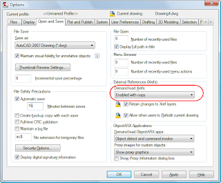
I had her go to the Options dialog > Open and Save and set the Demand Load Xrefs setting to Enabled with Copy. (This is the same as setting the XLOADCTL to 2.)
Once we set that, all was well.
What that does is makes a super-secret, temporary copy of an XREFd drawing so that you can manipulate it and modify it in multiple places. The odd thing about this problem is that it wasn't happening for DWG Xrefs. But who am I to look a gift horse in the mouth?

Thursday, November 06, 2008

Support Question of the Day: Proposed Profile After The Fact

Oh to be a full-time blogger. But then again, I wouldn't have the client interactions which keep me on my toes and inspire me to blog.


I've got a bunch of posts in progress but the following is a quickie that had me slack jaw for a few minutes.


Q: What happens if you create P&P sheets based off of an existing ground profile and want to add the proposed profile after the fact?


A: If you are creating P&P sheets in a separate drawing (which you ARE, AREN'T you???) and relying on the automatically created data references to pull data to your new drawing, any new profiles created will not automatically get added to the new drawing.


You have two options:

1) Recreate the sheets. (Which is a sucky option if you've gone and annotated and/or tweaked the P&P sheets.)

2) Manually create a data shortcut to the proposed profile.


  1. In your main drawing, change your Prospector to Master View.

  2. Find the Data Shortcuts area and right-click.

  3. Select New Data Shortcuts Folder.

  4. Create a folder for the data shortcut.

  5. Right-click again and pick Create Data Shortcuts.

  6. Put a check mark in the box for your proposed profile. Civil 3D will automatically grab the alignment too. That's normal.

  7. Jump to your P&P sheet drawing.

  8. In Prospector, browse to your data shortcuts.

  9. Locate the design profile, right-click and select Create Reference

  10. Repeat steps 7-9 for any additional P&P sheet drawing files.

Once the data shortcut has been made, updates will show up in the P&P sheet files as normal.

Civil Engineers Don't Make the News Much...

But when we do, isn't it comforting to know that the Los Angeles signal system is computer controlled?

More to come today.