Thursday, December 09, 2010

Don't Exit Civil 3D Before You Exit the Corridor Section Editor!

This was the topic of two separate tech support calls this week.  If points make a line, two problems make a blog post.

First, I want to talk about the corridor section editor in general.  It is an AMAZING, powerful tool.  If you build a corridor and need to tweak the cross section at a station or a range of stations, this is how you do it.  Some users attempt to modify the cross section views.  The section views are only a reflection of the model and cannot be used to change your corridor in any way.

The best way to get into the corridor section editor is to click on the frequency line at the station whose section you wish to modify.  From the context-sensitive ribbon, click Section Editor.

You will be taken into a purely data-driven view of your cross section.

Now that you are here, you can modify your cross section data just at this frequency line or at a range of stations.  The best way to modify this thing is through the parameter editor.  The parameter editor lists all the subassemblies and their current values as they are applied to the corridor.    In my opinion, use the numeric values to adjust your section whenever possible.

Sometimes you just need to adjust a daylight line by snapping it to a specific location on the exiting ground.  To graphically edit the section, hold down control while you click the daylight line.  You will see grips that you can use to move the line.  Be patient, it is a little slower than traditional line editing.

Here's the rub - you *can* modify the section graphically, but you cannot mix graphic changes with numeric changes.  If you went through and tweaked a lane width numerically then graphically edit the daylight line, the graphic edit blows away all your numeric changes.  So...you need to decide how you are going to make the modifications and stick with it.

Ok - here's where I get to my original point:  When you are done making your edits, save the drawing, then close the section editor using the ribbon!  Even if you are done for the day and want to go home, close the section editor first.

If you forget, or you are unfortunate enough to crash while in the section editor - don't fret.  When you open your drawing back up - things will look weird.  You are still in a modified coordinate system.  To get back to reality, go to your view tab and click the World icon.   Now, type PLAN at the command line, (hit enter), then W for world (hit enter).

Life will go back to normal...at least where Civil 3D is concerned.

Thursday, November 18, 2010

Flickery Dickory Dock, Civil 3D 2011 is Flickering Lots

This post is going out to my homeboy Troy who said something to me today along the lines of, "None of the blogs are giving any good information right now.  All anyone can talk about is AU!  I probably won't see any decent posts until late December."

Guilty as charged.  My challenge to fellow bloggers is: post something that has absolutely nothing to do with AU, before the Thanksgiving holiday.

In the last few days I've run into several people who are having problems with their Civil 3D 2011 graphics acting really annoying after service pack 1 was installed.   

Some are seeing the viewcube show up with a white background (even when their modelspace background is black!). 

Some are seeing this issue manifest itself as an error with "The configured Heidi driver cannot be loaded. Switching to default software driver."

Some are seeing "Exception in acmapworkspace.arx ARX Command" or "Unhandled exception 28ed90 (access violation reading 0x0028) at address blah blah blah..."

No matter how you are experiencing it, the root cause is the same: your graphics card is stressing out about Civil 3D. 

First thing to try:
Make sure your graphics card is up to snuff.  Is your card supported (or is it a cheap piece of crap that came with your box-store purchased machine)? 
If the card is supported, you may just need to update the driver.  Do that here: http://usa.autodesk.com/adsk/servlet/index?siteID=123112&id=6711848&linkID=9240698
If it is a cheap p.o.c. look for a new card here: http://www.nvidia.com/object/bfp_autocad_2011.html

Second thing to try (stolen from: http://usa.autodesk.com/adsk/servlet/ps/dl/item?siteID=123112&id=15851876&linkID=9240697):

  1. Inside of your application, type 3DCONFIG at the command line.
  2. In the dialog box that appears, select the Manual Tune button.
  3. At the top of the Manual Performance Tuning dialog box, toggle the 'Enable hardware acceleration' option. 
  4. Select OK and OK to return to the drawing workspace. 
  5. Repeat steps 1-4 again to toggle the 'Enable hardware acceleration' option back to its original setting.
Note that it not necessary to disable the hardware acceleration. However, toggling this setting should resolve the issues.


 Third thing to try:
Go to Analyze tab,Inquiry panel and under station tracker select Off.  
The key-in for it is AeccHideDrawingTips


Peace out.

Friday, November 12, 2010

Where to Stalk Me at Autodesk University

This information is also handy for those of you trying to avoid me.


As of today, there are only 18 days left until AU.  My schedule is quite full for the week.  Here's an overview of where you will find me during the conference. 
 
Monday:
  • Arrive in Las Vegas in the AM
  • Nap
  • Blogger Social 6-8pm
  • Speaker Social 6:30-9pm (I've heard the bloggers are more fun, so I'm just going to pop my head in with the speakers.)
Tuesday:
  • Sessions in the Civil Track all day
  • Nap
  • Go Out
Wednesday:
  • More classes in the AM
  • MY LAB: CV327-5L 1:30pm
  • Depending on how the lab goes I'll either be going to more sessions or looking into changing my identity.
  • Private Party: 9:30pm-?
Thursday:
  • Nurse expected hangover.
  • Sessions, sessions, sessions.
  • 1:00pm @ Autodesk University Theater "Meet the Authors" session w/ Rick Graham and yours truly. (I'm working on the next edition of Mastering Civil 3D)
  • Nap
  • I heard something about a gift card?
Friday:
  • Fly home. 

 See you there!


Wednesday, November 10, 2010

AUGI Cad Camp Minneapolis

Pictures of my boys at AUGI CAD Camp Minneapolis 2010. 

L to R: Robert Green, ME!, Rick Ellis

L to R: Eric Schubert, Mike Dunham, Mark Weizenegger of MasterGraphics

It was no AU, but by golly it was a good warm up.

I spoke about Point Cloud functionality in Civil 3D 2011.  A good time was had by all.

Monday, November 01, 2010

Civil 3D for Beginners - LIVE! One Night Only!

It will be cooler than Laser Floyd, but only involves a laser pointer.  Civil 3D for Beginners at AU!  

For those of you who were fortunate enough to get in (the class is filled up  - but I'm hoping for an encore) CV327-5L was the class to get.  This is a 1-hour hands-on lab (45 computers, 2 people to a computer).
Date/Time: 12/01/2010 - 1:30 PM

Here's what I'll be whipping through in the hour:

  • What is Civil 3D?  Is it BIM?
  • What is object-based design all about?
  • Importing points, creating a surface, changing the surface's style.
  • Changing alignment geometry and building a corridor.
  • P&P sheets and cross section sheets.
Here's a sneak-peek at a graphic from the handout explaining what comes with Civil 3D 2011 (on subscription). 

I simply cannot wait! I'll have four very talented assistants keeping everyone in line and on-track.  They may even be handing out candy (I'm gunning for the first ever 10-star speaker rating). 

See you there!

Friday, October 15, 2010

AutoCAD to Cricut Workflow (Alternate title: I'm a Cutter)

This post is dedicated to Theresa H. and the good people of Educause.

AutoCAD to Cricut Workflow:  Where Geeky Meets Crafty

Software needed:


Hardware needed:
  • Any computer running SCAL.
  • Cricut running firmware version 2.2 or higher. (These instructions will work for all cricuts - even the stupid cake one)
  • USB-Printer cable to connect your PC to the Cricut.

1- Draw your thing in Autocad.

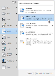
2- Export that thing as a BMP image.

3- In SCAL, go to Image Trace.


4- Browse to the BMP you exported from ACAD. And open it in the Autotrace Image dialog box.
5- Click Preview:

6- After you click OK, you will have your image in the SCAL cutting mat area.


7- Cut away!

Granted, someone with some mad printer driver hacking skills could probably get the Cricut to speak directly with AutoCAD.  As Jason says, a Cricut is really just a pen plotter with a knife.  If you know how to do this, I'd love to speak to you.

Enjoy!

Wednesday, October 13, 2010

Yay! You're Using Data Shortcuts...

...oh crap, you want to run a slope stake report. 

This post is based on a tech support call from a customer in South Dakota (the same one that inspired this post, coincidentally)

He is being a good boy and using data shortcuts to create his cross sections in a separate drawing from the corridor. 

However, when he goes to the toolbox to create a corridor slope-stake report he can't run the report in either drawing.  The corridor drawing tells him that he needs sample lines and the sample line drawing tells him he needs a corridor.

So, I ask, "Why don't you just re-create sample lines in the corridor drawing?  You don't need views, just the sample lines."
He replies, "Well, I would but we have a lot of non-even stations and would need to manually re-input those."


So poking around at the Create sections dialog, I envision a plan:
  1. WBLOCK the sample lines from the section drawing to a new block.
  2. Open the new block and explode everything until you are left with lines. 
    • This requires 3 explodes: from sample lines to blocks, from blocks to polylines, from polylines to lines.
    • Delete any alignment information that came along for the ride.
  3. Once the sample lines are lines zoom out so all sample lines are in view (even if that  means they are small little blobs on your screen) .
  4. Type FLATTEN at the CAD command line. 
    • This forces the lines to 0 elevation if they were not already.
    • The lines must all be at 0 for the next steps.
  5. Use PEDIT command to rejoin all the lines to polylines.
    • Use the Multiple option
    • Join the lines with 0.00 fuzz distance.
    • If this is done correctly you only need to run the pedit command once.
  6. Select all the polylines.
    1. Right-click and select Clipboard > Copy with Base Point
    2. When asked to specify basepoint type in 0,0
    3. Now, get back to your corridor drawing (if you have it open already, use the CTRL+Tab keys to switch between open files.)
    4. From the Home tab, Clipboard panel select Paste > Paste to Original Coordinates.
      • Yay - polylines!
      • At this point you will want to isolate the layer the polylines are on. 
    5. Now go to Home tab > Profile & Section Views Panel > Sample Lines
    6. When you're asked to pick the alignment, hit enter to pick from a list.  (because you've got the alignment turned off at this point right? )
    7. Click OK to create the sample line group.
    8. From the Create Sample line toolbar, click Select Existing Polylines.
    9.  Use big ol' crossing window to select the polylines.
    10. It should convert your polylines. 
      • I say *should* because this process may fail if any of the polylines are:
        • Not polylines
        • At an elevation other than 0.
    11. Go forth and run reports.
If someone knows a less step-y process, I'd love to hear it.  If you  have a script or something I'll be your bff.


Monday, October 11, 2010

WisDOT Files Where to Guide

I don't recall if I blogged this yet.  Better twice than not at all. 

So you've downloaded all the files from:
ftp://ftp.dot.state.wi.us/transp/roads/civil3d/

  • c3d_allusers.exe
  • c3d_installdir.exe
  • c3d_peruser.exe
  • c3d_perusercontentbrowserlibrary.exe
  • c3d_peruserlocal.exe
And you downloaded the entire directory WisDOTProjectTemplate, right?  Oh you haven't done that yet, probably because you are trying to work with the FTP site in Internet Explorer, when you really need to be working with it in Windows Explorer.   To switch views, from the browser, go to Page > Open FTP site in Windows Explorer.

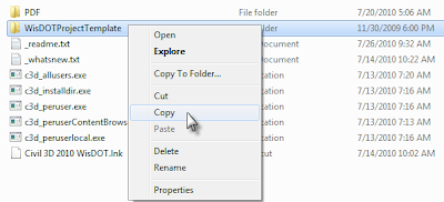
Right-click the directory and select copy.


Paste the directory under C:\Civil 3D Project Templates

If you are on Windows XP I've got mixed news:
1)  You should probably think about moving to Windows 7.  Windows 7 is much better at handling the memory needed to run Civil 3D well.  Besides, Microsoft will stop supporting XP soon.
2) The good news is that the Wisdot exe files will slide right onto your system.

Ok - so for the rest of us who are on Windows 7, you'll need to do some tweaking to get the WisDOT files placed correctly.

Double click the exe from WisDOT.
Click Run

You need to browse each and every time for the correct directory.
  • c3d_allusers.exe  needs to go to: C:\Program Data\AutoDesk\C3D 2010\enu\
    • This folder contains:
      • WisDOT intersection assemblies and underlying dlls.
      • WisDOT Figure prefix database
      • WisDOT design criteria XML files.
      • Several Wisconsin-specific reports
      • The SRV-to-PNTFLT.dvb mentioned in my last post
  • c3d_installdir.exe must be extracted to: C:\Program Files\AutoCAD Civil 3D 2010\
    • NOTE: You'll need to set this to C:\Program Files (x86)\AutoCAD Civil 3D 2010\  if you are on 64 bit system.
    • This folder contains:
      • Linetypes, font and supporting files
      • Help files for WisDOT custom subassemblies
  • c3d_peruser.exe gets extracted to: C:\Users\-user-\AppData\Roaming\Autodesk\C3D 2010\enu
    • NOTE:  This step will overwrite customizations to your c3d.cuix  file - I recommend keeping your own intact by renaming it before you copy.
    • This folder contains:
      • Plotter information
      • Toolpalette files
      • CUI file
      • DGN setups
  • c3d_perusercontentLibrary.exe goes to: C:\Users\-user-\Documents\Autodesk\
    • Overwrite & merge the My Content Browser Library
    • The WisDOT catalog file that will help make importing the subassemblies to your tool palette easier.
  • c3d_peruserlocal.exe gets extracted to: C:\Users\-user-\AppData\Local\Autodesk\C3D 2010\enu\
    • This contains all the WisDOT templates.
    • Merge and replace when prompted.
By extracting everything local, no changes need to be made in Options to your profile.

You can network many of these items, such as plotter settings linetypes, fonts and templates.  However, DO NOT attempt to network the subassemblies themselves.  I've never seen it work properly.

These files only work in Civil 3D 2010 - not at all in 2011.  Some of the reports may not work correctly on 64 bit systems (such as the SEUpdate.dll).

If the contents of this blog post confuse you, please get help trying to extract these files to the correct place.    

I am available for consulting on these matters through my employer


Tuesday, September 21, 2010

Don't Install Civil 3D...

...until you take my quiz to see if you are ready!

This quiz is just for fun - but talks about some real issues people run into when implemeting Civil 3D.

http://www.proprofs.com/quiz-school/story.php?title=are-you-ready-to-implement-civil-3d

Have fun.

Wednesday, September 15, 2010

FIXED: CAiCE SRV to Civil 3D 2010

This is a REPOST with fixed links.  My apologies to those who were unable to download due to the DVB file getting blocked by our server.  This repost has the files, but you will need to rename them after you save them to your harddrive.  The links won't expire!  w00t.


This post would not be possible without Rick Larson of WisDOT's DVB file. Thanks, Rick for letting me scam your program and spread it over the world!

These instructions apply to Civil 3D 2010, (will post 2011 version VBA file when it becomes available.)

Download the 2010 version of WisDOT's converter tool from:
srv-to_pntflt - Right-click and hit "Save target".  Be sure to rename the txt file extension to DVB

A test SRV file to play with can also be downloaded if you need one:
exist -  Extension rename to SRV is needed.


1. At the Civil 3D command line type: VBALOAD
2. Browse for the DVB file.

3. Click Enable Macros.


4. At the command line, type in VBARUN


5. Select the line that ends with “ReadSRVFile”
6. Click Run.
7. Browse for the SRV file you wish to convert.
8. Click Open


The result is 5 new files that are created in the folder containing the original SRV.
• *.srv.bld
• *.srv.flt
• *.srv.obs
• *.srv.pnt
• *.srv.wea

Civil 3D only uses the flt and the pnt files. The pnt is a space delimited PENZD file which can be imported as points. The flt file is a breakline file which can be added to a surface definition.


An example of how these can be used:

Since the point files tend to be large, we will not bother importing it as a survey file.

Create a surface.

Add the file using Point Files option under the surface definition.


Next, add breaklines.


Boom – you gotta surface.

Wednesday, August 18, 2010

Mastering Civil 3D 2011

I received my copy of Mastering AutoCAD Civil 3D 2011 last week and had plenty of time to read it while proctoring some Autodesk Certification Exams

It is excellent.  I've been up to my eyeballs in Civil 3D for the last four years and I can honestly say that I never stop learning tidbits here and there from my Mastering books.   James and Scott did an awesome job creating fresh information and fine-tuning this encyclopedia of Civil 3D knowledge.

(Yes, guys I will put a glowing 5 star review on Amazon too!)


So, that leaves me with the question...do I pitch/recycle my first one?  All of my clients have upgraded to at least 2009, leaving the 2008 book as a mere memento of a time that I didn't know my ass from a negative slope grading object.

So I turned my 2008 book into a minibar:

Believe me, the first cut was hard.   For one thing I've always been taught to revere the printed word.  Second, cutting into Dana, James, Mark & Jason's  pivotal work felt a little bit like cutting up a high school yearbook. 

Despite this book desecration/minibar transformation, the world should know I have the deepest respect and admiration for the authors. 

BOTTOMS UP!

Tuesday, August 17, 2010

Super Helpful Help

Hey all!

I know, I know I should blog more often.  But it is summer and there are State Fairs to attend,  beaches to lay on and sunshine to absorb. 

Here's something I JUST noticed today... the help in 2011 knows object names and uses them to help you navigate procedures.  It picks the name of the object at the time you hit F1. 


For all I know, it's done this since 2005, but I'm just noticing it now.  It's cool.  It makes me feel safe and happy in the Help docs. 

Have a great week!

Friday, July 09, 2010

Civil 3D Haiku

Eric is a true renaissance man.  Engineer and poet wrapped in one.

Tuesday, July 06, 2010

Back to Basics: Autocad Linetypes

SQOTD:
K.M is doing a plat that has an electrical line type that has an “E” in the line. He was hoping to get the “E” to repeat more often and make the text larger so that it can be seen when plotted. How can we do this?

Answer:
To create a new line type the first step is to go out and find the linetype file (acad.lin) stored on your computer under:

C:\Documents and Settings\\Application Data\Autodesk\C3D 2010\R18.0\enu\Support

Notes:
  • Vista or Win7 users will find this: C:\Users\\AppData\Roaming\Autodesk\C3D 2010\R18.0\enu\Support 
  • For Civil 3D 2011 the path will be ...blah\blah\blah\Autodesk\C3D 2011\enu\Support (substitute appropriate Windows AppData path instead of the blahs.)

Double-click the ACAD.lin file and open it up with notepad.

You’ll see the list of all the “guts” of the linetypes.

Scroll down to the bottom to see a category called user defined linetypes.

You’ll end up pasting something like this at the bottom of the file.

*Electric_LINE,Elec ----E----E----E----E----E----E--
A,.5,-.2,["E",STANDARD,S=.1,R=0.0,X=-0.1,Y=-.05],-.25


Save and close the LIN file, then you’ll be able to add the line in AutoCAD.

Avoid adjusting the size of the line through the acad.lin file, unless you want it to change for all drawings going forward!

The size of the line should be controlled on the front end of Civil 3D.

Make sure the MSLTSCALE variable is set to 1. <--this means the linetypes will adjust with the annotative scale

Make sure the PSLTSCALE variable is also set to 1. <--this means the linetypes will adjust for viewport scale

If you need to change an individual line type’s scale use the Linetype scale setting in regular ACAD properties (civil 3d styles have this setting too). To change all the lines in the drawing together type in LTSCALE at the command line (however, if you have MSLTSCALE and PSLTSCALE set correctly, you shouldn’t have to radically change this.)


Now, I know I'm going to get an email or comment saying, "Why didn't you tell him to just use the Make Linetype command under express tools?"  I do think that is a swell tool to use after you understand what is happening in the ACAD.lin file. 

Friday, July 02, 2010

Section View Station Labels

It is about damn time I posted.  I have been all over the US vacationing, learning VB.NET and teaching Civil 3D.

The following post was inspired by a customer of mine who does a lot of work for South Dakota DOT.  He wanted to label the station inside the graph, but the grid lines were harshing his buzz.  There is no way (to my knowledge) to force the display order of this item.

What we ended up doing was forcing our hand by putting the station label in the Centerline label inside of the band style.   However, there is no station value component inside the band!
Sooo, we jumped into the title text area and copied out the text.


Then we jumped into the band style and pasted in Section View Station into the text component editor.


Bada-bing!  It worked.  You can now use good ol' display order to bring the label to the front.

Happy 4th! Don't blow off any appendages.

Tuesday, June 01, 2010

Raster Design Object Enabler Available for 2011 Products!

http://usa.autodesk.com/adsk/servlet/ps/dl/item?siteID=123112&id=15201709&linkID=9240698

Just remember to download the correct version fro your operating system, as there are downloads for 32bit and 64 bit!

Monday, May 31, 2010

Interesting Intersections I've crossed

This week I ran into two interesting examples of alignments that just didn't play well with the automated intersection design tools.

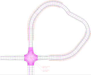
Case 1- The Loop:
It isn't unusual for an alignment to cross itself, however the intersection tool won't recognise the crossing location.  Of course, the easy answer is to split it into 2 alignments. However, I wanted to build the intersection the pre-2010 way, manually creating curb return profiles and corridor regions the "old fashioned" way to see if I ran into any hiccups. 


I was worried that C3D might get confused with the whole "Target nearest to offset" thing in the corridor parameters, however this ended up building without  problem.  The most difficult part was getting the right OSNAP for throwing on the station label at the intersection (as seen in the screen cap).  I used trial and error until I got what I wanted.

One of the big things you need to remember in creating manual intersections is to make sure your crowns match. 

To manually lock a PVI just jump into the profile geometry editor. Use the select PVI to make sure you're locking the correct one and set the Lock option in geometry to True.


Case 2 - Two Ts:
This scenario came to me this week from a client.  Two J-shaped subdivision roads T into each other.  The first intersection builds without a hitch. The second intersection will not go so well.  In my client's case it was creating wacky profiles (deleting vertical curves and locking the profile at the first intersection).  When I tried it myself, I got the message, "The primary road for this T-junction will result in a circular dependency with the existing intersections."  In other words, Civil 3D gets just as confused as the friend who you tell, "Pick me up at the intersection of Jefferson and 3rd Ave..."  Which one?!

Your best bet for fixing this case is two split one of the alignments into two.  Of course you could do this one the pre-2010 way as well.

Hope this info comes in handy someday.

Friday, May 21, 2010

VOTE FOR AU CLASSES!


Only a few more days left to vote for my classes at AU: http://www.autodeskevents.com/au2010/index.cfm?event=voting.login
Vote for your favorite classes...don't make me bribe you with candy!

Civil 3D Craft Project: Migrating Eagle Point Field Codes

Are you an Eagle Point user migrating to Civil 3D?
Are you a Civil 3D user who just hates the squirrely behavior of the description key editor?

If you answered YES to any of the above questions, I have some good news for you.  I've developed a method of getting Eagle Point field codes over to Civil 3D without having to retype any of the names.  You can also use this technique for typing in your description keys in a spreadsheet and migrating them over, thus avoiding the annoying editor. 

(If you find this process too tedious and want me to do it for you, donate $50 bucks (see button right) and email me the exported EP codes.  I'll send it back to you as a DWG from which you can move the completed Description keys.)

DISCLAIMER:  The Description Key, Format and layer columns go across without a hitch.  When the process is all done, you still need to set your styles for marker and point label. 


What you will need:
  • Eagle Point
  • Civil 3D
  • Any version of Microsoft Access
  • Any version of Excel
  • A copy of the "dummy" Land Desktop file and my handy-dandy converter spreadsheet available HERE.
1) In Eagle Point, go to System then Node (Field Code) Library


2) Click the Manage Field Codes button.
3) Click Export.  Save the file pretty much anywhere (as long as you remember where you put it).  Give the file a full name such as Export-to-C3D.csv.

4) Double-click your new CSV file and let it open in Excel.
5) Copy your information from columns A through Q.
6) Open up the spreadsheet EP_Convert.xlsx
7) Make sure you are on the worksheet tab called Eagle_Point
8) Click your cursor in cell A2 (the first blank one), and paste.
9) Switch to the worksheet tab called Default. 

Your Eagle Point information is now in the correct format for bringing into an Access table. 
10) Save the Excel file.

12) Close up all your Excel files.  Fire Up Access by double clicking the Default.mdb.

13) If Access prompts you to update the database to the latest format, click yes.    If a conversion errors table is created, delete it.

 If it doesn't prompt you, just be glad and move on to the next step.

14) Go to External Data.  Click Excel.

15) Browse for the EP_Convert.xlsx file that contains your stuff.
16) Toggle on "Append a Copy of the records to the table DESKEYS".  Click OK.

 
17) IMPORTANT: Make sure the worksheet Default is highlighted.

 
18) Click next until the import finishes.   Access should automatically recognise the column headings. 

Double click the table DESCKEYS to check out the new data you imported. If you want to add or modify your codes this would be a good place to do so.


19) Save the MDB as a 2000 format file. 


20) Put the database (mdb) file in a folder called DescKey.  Put the DescKey folder in a folder called Cogo. Put the Cogo folder in a folder called EP Import.

21) Fire Up Civil 3D (yay! Finally!) Open up the template where you want these keys to reside. 
22) Go to Insert tab > Land Desktop.  Browse to the folder one level up from wherever you put the EP Import folder. You know you are in the right spot when EP Import is listed in the Project name.  Click OK.


23) If you did everything correctly, Civil 3D will pop up a message that says "Description Keys migration completed!"
24) Click OK.
25) Lastly, you'll need to get to work setting styles in the description key editor, but that's easy!

Friday, May 07, 2010

'Nother Non-techincal Quickie

I've changed my comment policy to allow ANYONE to comment.  Previously I required a Google account. 

I'm still moderating comments and reserve the right to reject stuff - but for all of you who have emailed me with comments - this one is for you!

Of course, I always do enjoy your email messages and I do respond to them as time permits.

Have a great weekend!

Wednesday, April 14, 2010

Quick Update - Non Technical

Hey all. Just a quickie to let you know that I'm not dead. I've got several posts 2/3 written and haven't had time to clean them up for release.

In the coming weeks you can expect the following posts:

  • It's a "Group" Thing
  • Facts and Figures
  • Forcing Map 2011 to install as 32 bit on a 64 bit Machine

In the meantime you can follow me on Twitter again if you are so inclined. I'm now @LouisaHolland . I rejoined with a new mindset (thanks to @Civil3diva). Did you know its OK to miss people's Tweets? Crazy. If you follow me you'll get about 40% me whining about work, 30% quasi-philosophical musings, 27% crap, and 3% vaguely relevant software Tweets.

Wednesday, March 10, 2010

AutoCAD Skills for C3D Users

Part 3 of a 10 part series...wait..or was it part 4 of a 12 part series? Oh forget it, here's the whole document!

If you are about to learn Civil 3D 2010 and are coming from an old version of AutoCAD, Microstation or even BricsCAD/IntelliCAD, you’ll need to brush up on your AutoCAD knowledge.

The attached PDF will take you through the bare-bones basics of AutoCAD in preparation to learn Civil 3D 2010.

AutoCAD Skills for C3D Users

If you are taking one of my upcoming classes, I want you to memorize this and sleep with it under your pillow.

BTW My upcoming classes that are open to the public are:
March 22-25th in Madison, WI
April 22-23, 29-30 in Waukesha, WI
Click here to register.

Tuesday, March 09, 2010

All About Breaklines

Spring is around the corner which means the last submittals are due before construction season here in the north. It has been a crazy busy few months for me and my clients, but I'll squeeze in a quick blog post.


Adding breaklines to a surface is simple. From Prospector, expand the surface definition to which you want to add the breakline. Right-click on the Breakline area and select Add. Now you have several options which we will discuss in detail...


There are five options when adding breaklines to a surface:
• Standard
• Proximity
• Wall
• From file
• Non-destructive


The first screen-cap shows the triangles on a surface before a breakline is added to the surface.
Compare the spot elevations in the examples to see what is changing with the surface depending on the type of breakline.

The example breakline has elevations at each vertex of 972.0, 967.6 and 969.0.


The second image shows a standard breakline added to the surface. Standard breaklines are the most common type of breakline. Civil 3D uses the line’s vertex elevations and adds them to the surface exactly as they are. Triangles are created and align with the breakline.


The third screen-cap shows the breakline added as Proximity.
Elevations from proximity breaklines are ignored and X,Y and Z values are inherited from the nearest triangle vertex. The black line is the original line added as proximity. The green line is how Civil 3D sees it.

This type of breakline can be used when the XY values for a line are known, but the elevations are
unknown.


The fourth picture shows a wall breakline in plan view. A wall breakline is like adding two breaklines, one at the real breakline elevation and one at the height you specify*.


Here is a schematic of the wall breakline in section view with the offset side to the left. The black dot represents the location of the feature line. The cyan squares represent existing surface points.


This 5th screen-shot is an example text file in the correct format to be a breakline file. Breakline files can be either space or comma delimited. Breakline files MUST be in the format Easting, Northing, Elevation.

The S in the files denotes the start of a line.

Once the file is imported the elevations are treated exactly like a standard breakline.


Non-destructive breaklines do not change the elevation of the surface in any way, but they do change the triangles at the location of the breakline. New triangles are formed but the vertex elevations for those triangles are interpolated from the surface.


*When it comes to wall breaklines there is a teensy, tiny offset in the XY plane. This offset of 0.001' prevents the wall from being perfectly vertical. Civil 3D surface models can't contain caves, overhangs or vertical walls.

I hope you enjoyed this wildly compelling explanation of breaklines. Thanks to K.W. of Seattle for inspiring me!