Friday, October 15, 2010

AutoCAD to Cricut Workflow (Alternate title: I'm a Cutter)

This post is dedicated to Theresa H. and the good people of Educause.

AutoCAD to Cricut Workflow:  Where Geeky Meets Crafty

Software needed:


Hardware needed:
  • Any computer running SCAL.
  • Cricut running firmware version 2.2 or higher. (These instructions will work for all cricuts - even the stupid cake one)
  • USB-Printer cable to connect your PC to the Cricut.

1- Draw your thing in Autocad.

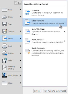
2- Export that thing as a BMP image.

3- In SCAL, go to Image Trace.


4- Browse to the BMP you exported from ACAD. And open it in the Autotrace Image dialog box.
5- Click Preview:

6- After you click OK, you will have your image in the SCAL cutting mat area.


7- Cut away!

Granted, someone with some mad printer driver hacking skills could probably get the Cricut to speak directly with AutoCAD.  As Jason says, a Cricut is really just a pen plotter with a knife.  If you know how to do this, I'd love to speak to you.

Enjoy!

Wednesday, October 13, 2010

Yay! You're Using Data Shortcuts...

...oh crap, you want to run a slope stake report. 

This post is based on a tech support call from a customer in South Dakota (the same one that inspired this post, coincidentally)

He is being a good boy and using data shortcuts to create his cross sections in a separate drawing from the corridor. 

However, when he goes to the toolbox to create a corridor slope-stake report he can't run the report in either drawing.  The corridor drawing tells him that he needs sample lines and the sample line drawing tells him he needs a corridor.

So, I ask, "Why don't you just re-create sample lines in the corridor drawing?  You don't need views, just the sample lines."
He replies, "Well, I would but we have a lot of non-even stations and would need to manually re-input those."


So poking around at the Create sections dialog, I envision a plan:
  1. WBLOCK the sample lines from the section drawing to a new block.
  2. Open the new block and explode everything until you are left with lines. 
    • This requires 3 explodes: from sample lines to blocks, from blocks to polylines, from polylines to lines.
    • Delete any alignment information that came along for the ride.
  3. Once the sample lines are lines zoom out so all sample lines are in view (even if that  means they are small little blobs on your screen) .
  4. Type FLATTEN at the CAD command line. 
    • This forces the lines to 0 elevation if they were not already.
    • The lines must all be at 0 for the next steps.
  5. Use PEDIT command to rejoin all the lines to polylines.
    • Use the Multiple option
    • Join the lines with 0.00 fuzz distance.
    • If this is done correctly you only need to run the pedit command once.
  6. Select all the polylines.
    1. Right-click and select Clipboard > Copy with Base Point
    2. When asked to specify basepoint type in 0,0
    3. Now, get back to your corridor drawing (if you have it open already, use the CTRL+Tab keys to switch between open files.)
    4. From the Home tab, Clipboard panel select Paste > Paste to Original Coordinates.
      • Yay - polylines!
      • At this point you will want to isolate the layer the polylines are on. 
    5. Now go to Home tab > Profile & Section Views Panel > Sample Lines
    6. When you're asked to pick the alignment, hit enter to pick from a list.  (because you've got the alignment turned off at this point right? )
    7. Click OK to create the sample line group.
    8. From the Create Sample line toolbar, click Select Existing Polylines.
    9.  Use big ol' crossing window to select the polylines.
    10. It should convert your polylines. 
      • I say *should* because this process may fail if any of the polylines are:
        • Not polylines
        • At an elevation other than 0.
    11. Go forth and run reports.
If someone knows a less step-y process, I'd love to hear it.  If you  have a script or something I'll be your bff.


Monday, October 11, 2010

WisDOT Files Where to Guide

I don't recall if I blogged this yet.  Better twice than not at all. 

So you've downloaded all the files from:
ftp://ftp.dot.state.wi.us/transp/roads/civil3d/

  • c3d_allusers.exe
  • c3d_installdir.exe
  • c3d_peruser.exe
  • c3d_perusercontentbrowserlibrary.exe
  • c3d_peruserlocal.exe
And you downloaded the entire directory WisDOTProjectTemplate, right?  Oh you haven't done that yet, probably because you are trying to work with the FTP site in Internet Explorer, when you really need to be working with it in Windows Explorer.   To switch views, from the browser, go to Page > Open FTP site in Windows Explorer.

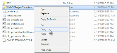
Right-click the directory and select copy.


Paste the directory under C:\Civil 3D Project Templates

If you are on Windows XP I've got mixed news:
1)  You should probably think about moving to Windows 7.  Windows 7 is much better at handling the memory needed to run Civil 3D well.  Besides, Microsoft will stop supporting XP soon.
2) The good news is that the Wisdot exe files will slide right onto your system.

Ok - so for the rest of us who are on Windows 7, you'll need to do some tweaking to get the WisDOT files placed correctly.

Double click the exe from WisDOT.
Click Run

You need to browse each and every time for the correct directory.
  • c3d_allusers.exe  needs to go to: C:\Program Data\AutoDesk\C3D 2010\enu\
    • This folder contains:
      • WisDOT intersection assemblies and underlying dlls.
      • WisDOT Figure prefix database
      • WisDOT design criteria XML files.
      • Several Wisconsin-specific reports
      • The SRV-to-PNTFLT.dvb mentioned in my last post
  • c3d_installdir.exe must be extracted to: C:\Program Files\AutoCAD Civil 3D 2010\
    • NOTE: You'll need to set this to C:\Program Files (x86)\AutoCAD Civil 3D 2010\  if you are on 64 bit system.
    • This folder contains:
      • Linetypes, font and supporting files
      • Help files for WisDOT custom subassemblies
  • c3d_peruser.exe gets extracted to: C:\Users\-user-\AppData\Roaming\Autodesk\C3D 2010\enu
    • NOTE:  This step will overwrite customizations to your c3d.cuix  file - I recommend keeping your own intact by renaming it before you copy.
    • This folder contains:
      • Plotter information
      • Toolpalette files
      • CUI file
      • DGN setups
  • c3d_perusercontentLibrary.exe goes to: C:\Users\-user-\Documents\Autodesk\
    • Overwrite & merge the My Content Browser Library
    • The WisDOT catalog file that will help make importing the subassemblies to your tool palette easier.
  • c3d_peruserlocal.exe gets extracted to: C:\Users\-user-\AppData\Local\Autodesk\C3D 2010\enu\
    • This contains all the WisDOT templates.
    • Merge and replace when prompted.
By extracting everything local, no changes need to be made in Options to your profile.

You can network many of these items, such as plotter settings linetypes, fonts and templates.  However, DO NOT attempt to network the subassemblies themselves.  I've never seen it work properly.

These files only work in Civil 3D 2010 - not at all in 2011.  Some of the reports may not work correctly on 64 bit systems (such as the SEUpdate.dll).

If the contents of this blog post confuse you, please get help trying to extract these files to the correct place.    

I am available for consulting on these matters through my employer